A capacitor is a device used in electronics that stores energy and electric charge. The parallel plate capacitor is one of the most basic and significant types of capacitors. It is extensively utilised in electronic circuits.
In general, a capacitor consists of two conductors placed close to each other. We can say for example, two plates kept parallel to each other.
One of the plates is given positive charge (positive plate) and other is given negative charge (negative plate). Such that Q = CV, where Q is the charge on the positive plate and
V = V+ – V–.
If plates are large compared to the separation between them, then electric field between them is uniform and perpendicular to the plates except for a region near the edge (called fringing effect).
Capacitor
A capacitor is an electronic component that stores and releases electrical energy in a circuit. It consists of two conductive plates separated by an insulating material called the dielectric. When a voltage is applied across the plates, an electric field develops, and charge accumulates on the plates.
What is a Parallel Plate Capacitor?
Two flat, conductive plates arranged parallel to one another make up a parallel plate capacitor. There is classically air or another insulating substance known as a dielectric between these plates, which are spaced apart by a modest amount.
One plate gets positively charged and the other gets negatively charged when a voltage is placed across the plates (by connecting them to a battery).
The capacitor stores energy in the form of an electric field between the plates because the insulating material between them prevents charges from moving from one plate to the other.
How Does it Work?
Assume that a battery is attached to the plates. One plate, which is positively charged, will have electrons drawn off it and pushed onto the other, which is negatively charged.
An electric field is created from the positive plate to the negative plate as a result of the potential difference (voltage) that is created between the plates.
The capacitor will retain its charge as long as it is linked to the battery because of this electric field. After being detached, the charges stay on the plates until they are reconnected in a circuit that enables them to move and perform practical tasks, such as supplying electricity to a camera’s flash.

Formula for Capacitance
Capacitance is a measure of a capacitor’s capacity to hold charge. A parallel plate capacitor’s capacitance is determined by:
The area (A) of the plates
The distance (d) between the plates
The dielectric material between them
The formula is:
C = ε0εrA / d
Where:
C = Capacitance (in Farads)
ε0 = Permittivity of free space (8.85×10⁻¹² F / m)
εr = Relative permittivity of the dielectric (also called dielectric constant)
A = Area of each plate
d = Distance between the plates
Capacitance is a measure of a capacitor’s capacity to hold charge. A parallel plate capacitor’s capacitance is determined by
What is a Dielectric?
An insulating substance positioned in between a capacitor’s plates is called a dielectric. Air, paper, glass, mica, and plastic are examples of common dielectrics.
When a dielectric is inserted:
It reduces the electric field
Allows more charge to be stored
Increases the overall capacitance
This occurs when the dielectric’s molecules align to partially cancel out the electric field between the plates, which facilitates the storage of more charge.
Energy Stored in a Capacitor
The energy stored in a capacitor is given by the formula:
U = 1 / 2CV2 Where:
U = Energy stored (in joules)
C = Capacitance
V = Voltage across the plates
This stored energy can be used later in electronic devices, such as cameras, radios, or even electric cars.
Applications of Parallel Plate Capacitors
Energy storage in electronic circuits
Smoothing out fluctuations in power supply
Timing elements in oscillators
Tuning circuits in radios and televisions
Sensor applications, such as measuring pressure or humidity.
Force between plates of a capacitor:-
The plates of parallel plate capacitor exert attractive force on each other. The electric field of one charge exerts force on the other charge.
Summary
In electronics, the parallel plate capacitor is a effective part. We can learn more about electric fields and energy storage by understanding its design, operation, calculations and applications.
An insulating substance (dielectric) is placed between two flat, parallel metal plates that are spaced a short distance apart to form a parallel plate capacitor. In the electric field that exists between the plates, it stores energy and electric charge.
The capacitance depends on:
The area (A) of the plates – larger area means more capacitance.
The distance (d) between the plates – smaller distance increases capacitance.
The dielectric material – materials with a higher dielectric constant increase capacitance.
C = ε0εrA / d
Where:
C = Capacitance
ε0 = Permittivity of free space
εr = Dielectric constant
A = Area of the plates
d = Distance between the plates
By decreasing the effective electric field, a dielectric is inserted, increasing the capacitance and enabling the capacitor to hold more charge at the same voltage.
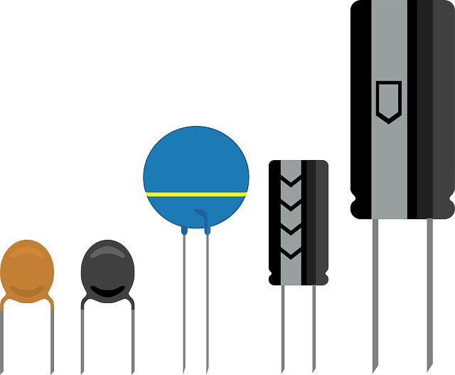
The SI unit of capacitance is the Farad (F). However, in practical circuits, capacitance is usually measured in microfarads (µF), nanofarads (nF), or picofarads (pF).
The energy stored in a capacitor is given by:
U = 1 / 2CV2
Where U is the energy (in joules), C is the capacitance, and V is the voltage across the plates.
Parallel plate capacitors are used in:
Electronic circuits for energy storage
Power supply smoothing
Timing devices
Tuning radios and communication devices
Sensors (e.g., in touchscreens, pressure sensors)